Install and Configure Transflo DMS Field Imaging
As an administrator, use this article to install and configure Transflo DMS Field Imaging. The Transflo DMS Field Imaging application is used for remote scanning and indexing. Field Imaging stores images in a local database and transfers batches to a central product environment. Optional features include host validation and the ability to read multiple bar codes.
-
To set up the Field Imaging application, use the Field Imaging Administration utility. This article explain how to configure the tabs in the Field Imaging Administration utility.
-
Configure the Remote Transfer program installed with the Field Imaging installation program to transfer TIFF images and associated index information to the imaging server.
-
The General tab is explained in .
-
For instructions on configuring the Index tab, see .
-
The Log tabs is explained in
-
The Scan tab is covered in .
-
The Transfer Info and Transfer Type tabs are covered in .
-
For an explanation of the Barcode and Zoom tabs, refer to .
-
To configure the HEC tab, follow the instructions in .
-
For an explanation of the Field Imaging Integration COM Library see .
Minimum Hardware Platform
-
Processor: 800MHz
-
RAM: 512MB
-
Disk Space: 5GB
-
Screen Resolution: 1024x768
Recommended Hardware Platform
-
Processor: 1 x 1.8Ghz
-
RAM: 1GB
-
Disk Space: 5GB
-
Screen Resolution: 1024x768
Supported Operating System Platforms
-
Microsoft Windows® XP Professional, SP3
-
Microsoft Windows® Vista Business
-
Microsoft Windows® 7 (x86 and x64 editions)
The following is a list of required third-party software:
-
Kofax VRS
Third-Party Software Installation Considerations on Microsoft Windows® 7 x64
Kofax VRS
Only Kofax VRS 4.5 or above is supported on Windows® 7 x64.
Product Limitations & Assumptions
There is a limitation on the characters that can be entered in the Index Fields.
You may only enter: A, B, C, D, E, F, G, H, I, J, K, L, M, N, O, P, Q, R, S, T, U, V, W, X, Y, Z, 1, 2, 3, 4, 5, 6, 7, 8, 9, 0, [space], /, :. and . .
The backslash will be replaced with the empty space instead (i.e. 1\1\1111 will be replaced as 1 1 1111).
Alphabetic characters will be changed to upper case at Index time.
Accessing Field Imaging Administration
The Field Imaging administration function is accessed from the main Field Imaging interface.
To start the Field Imaging application, click the Start button on the Windows taskbar, point to Programs, point to TRANSFLO®, and click Field Imaging.
The Field Imaging interface opens.
To start the administration function, click the Admin button at the bottom-right edge of the screen or press [F5] on your keyboard.
Note: If Field Imaging has never been configured (e.g., this is the first time that Field Imaging has been run), the administration interface is displayed automatically.
Note: If Field Imaging is running on Windows® 7 x64, make sure you run Field Imaging as a local administrator in order to properly configure Field Imaging.
The Field Imaging Administration dialog box opens.
The Field Imaging application is configured via the tabs in this dialog box.
Administration with Password
If you have Require password for administration configured in the General tab, the Administration password window opens before the Field Imaging Administration window opens.
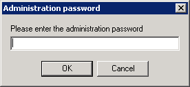
Enter the administration password in the Please enter the administration password box, and click OK.
The Field Imaging Administration dialog box opens.
If you forget the administration password, you can reset it by following the steps below.
1. Open a windows Command prompt (cmd.exe).
2. Navigate to the Field Imaging installation directory.
By default it is,
C:\Program Files\Pegasus TransTech\Field Imaging
3. Type "FieldImg /MasterKey" and press [Enter].
The main Field Imaging window opens.
4. Click the Admin button.
The Administration password window opens.
5. Type “MasterKey” in the Please enter the administration password box ,and click OK.
The Field Imaging Administration dialog box opens.
Introduction
Overview
This Knowledge Base is designed to provide you with a general understanding of Field Imaging.
When you have finished reading this Knowledge Base, you should be able to scan and index Documents using Field Imaging.
This Knowledge Base contains step-by- step instructions for each topic, making it a useful reference.
Main Functions
The TRANSFLO® Field Imaging application functions are summarized below.
For additional information regarding the functions listed below, refer to the appropriate chapter of this manual.
-
Scanning - The scanning feature is used to scan Documents into the application. Once all of the Documents have been scanned into the system, a batch is created.
-
Indexing - Allows you to enter Index Field information based on the index values that were established by your Field Imaging administrator in the Field Imaging Configuration window.
-
Searching - Allows the user to search previously scanned and indexed Documents based on the Index Field values.
Field Imaging Process Flow Diagram
The diagram below provides a high-level view of the internal processes of Field Imaging:
Starting Field Imaging
To start TRANSFLO® Field Imaging, click the Start button on the Windows taskbar, point to Programs, point to TRANSFLO® , and click Field Imaging.
Field Imaging Windows
Field Imaging includes two primary windows designed to allow you to easily navigate through the system.
Numerous keyboard shortcuts are provided to allow you to navigate through the system without using a mouse.
The images below provide an brief overview of the components used in Field Imaging.
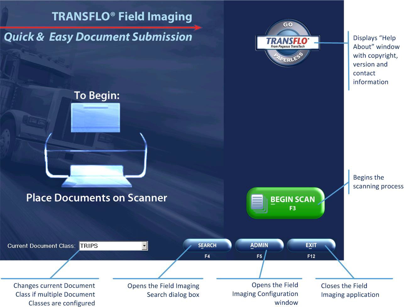
Field Imaging Main Window
The main Field Imaging window is shown in the image below.
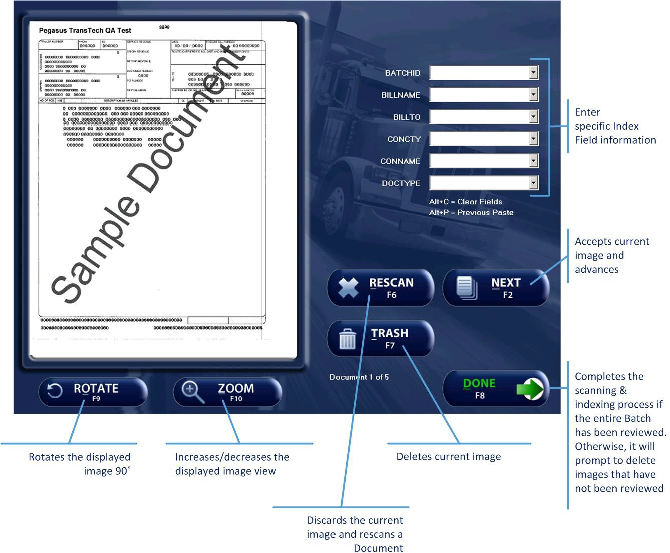
Field Imaging Indexing Window
The Field Imaging indexing window is shown in the image below.
Standard Shortcuts
The following is a list of keyboard shortcuts that will enable you to navigate through Field Imaging without using a mouse.
|
Control Type |
Keystroke | Action |
|---|---|---|
|
Editing a Text Box |
[Home] [Ctrl] + [Home] |
Moves the cursor to the beginning of the line. |
|
|
[End] [Ctrl] + [End] |
Moves the cursor to the end of the line. |
|
Function Keys & Keyboard Commands |
[F2] [Alt] + [N] |
On the Field Imaging indexing window switches to the next Document in the batch if there are multiple pages, and you are not on the last image. |
|
|
[F2] [Alt] + [S] |
Scans one or more Documents into the batch if you are viewing the final Document in the batch. |
|
|
[F3] [Alt] + [B] |
On the main window scans the Documents in the scanner and opens the Field Imaging indexing window. |
|
|
[F4] [Alt] + [E] |
On the main window opens the Search dialog box. Allows you to enter Index Field values that can be used to conduct searches for previously scanned and indexed Batches stored in the system. |
|
|
[F5] [Alt] + [A] |
On the main window opens the Field Imaging Configuration windows and allows authorized users to configure the Field Imaging administration settings. |
|
|
[F6] [Alt] + [R] |
Clears the current index values and re-scans the Documents. |
|
|
[F7] [Alt] + [T] |
Discards the current Document in the batch. |
|
|
[F8] [Alt] + [D] |
Completes the scanning and indexing process. |
|
|
[F9] [Alt] + [O] |
Rotates the image 90 degrees. |
|
|
[F10] [Alt] + [Z] |
Increases or decreases the displayed size of the scanned image being viewed. Changes from Zoom to Out when selected, to allow you to return to the original image viewing size. |
|
|
[F12] [Alt] + [X] |
On the main window exits the Field Imaging application. |
|
|
[Tab] |
Moves forward through the Index Fields. |
|
|
[Shift] + [Tab] |
Moves backwards through the Index Fields. |
|
|
[Alt] + [F4] |
Closes the current window. |
|
|
[Alt] + [C] |
Clears all of the Index Fields for the current image. |
|
|
[Alt] + [P] |
Returns the index value of the previous image for the selected box. |
Configure the General Settings
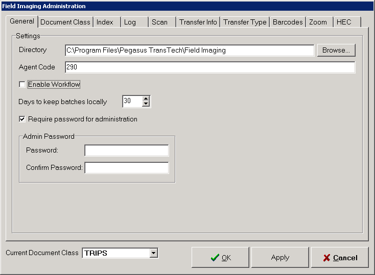
This topic explains how to configure basic settings for the Field Imaging installation via the General tab. These settings include the root Document directory and the Agent Code.
The General tab is the default tab displayed when the Field Imaging Administration dialog box appears.
To configure this tab:
1. The Directory box is the root directory of where your Documents are stored.
It is best not to change this path.
Warning: If you have multiple Document Classes configured and you change the path in the Directory box, you will loose all your Document Classes except the default Document Class.
2. In the Agent Code box, type the unique code for this Field Imaging station.
3. To enable TRANSFLO® Workflow to create Workflow Cases for Batches created with Field Imaging, select the Enable Workflow check box.
4. (Optional): To require an administrator to enter a password when opening the Field Imaging Administration window select the Require password for administration check box.
The Admin Password group box opens below the Require password for administration check box.
5. Enter the password in the Password box.
Re-enter the password in the Confirm Password box.
6. When you have finished configuring the General tab, click the Apply button to save your changes
Click the next tab that you wish to configure, or click OK to close the Field Imaging Administration dialog box and return to the main Field Imaging interface.
Document Class Settings
Introduction
This topic explains how to define the Document Classes that are used define a set of Index Fields on the Document Class tab.
You can also delete Document Classes from the Document Class tab.
In previous versions of Field Imaging Document Classes were referred to as Bases.
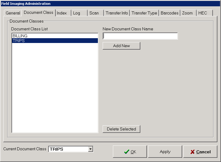
Configuring the Document Class Tab
To configure the Document Class tab, perform the following steps for each Document Class being used:
1. Type the name of the Document Class in the New Document Class Name box.
2. Click the Add New button.
The Document Class is added to the list in the Document Class List box.
The Document Class is added to the list in the Current Document Class drop down.
3. To remove a Document Class from the Document Class List box, click on it to select it.
Click the Delete Selected button.
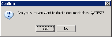
4. A Confirm message box opens to make sure you really want to delete the selected Document Class.
Click Yes.
5. The Document Class is removed from the Document Class List box and the Current Document Class drop down.
Selecting the Current Document Class
Only one Document Class can be made available for the user to Scan and Index documents at one time.
To select the Document class that will be available to the end user, select it from the Current Document Class drop down.
The newly selected Document Class is saved as the current Document Class when you change it in the Current Document Class drop down.
If you change the current Document Class, for example, and click the Cancel button on the Field Imaging Administration window, Field Imaging will restart and the newly selected Document Class will be the current Document Class.
Note: If you have multiple Document Classes configured, Remote Transfer will send all pending Documents from all Document Classes at the same time.
Indexing Settings
Introduction
This topic explains how to define the properties of the indexing interface presented to Field Imaging Users.
These settings include the Index Field labels, default values, and whether or not each field is required.
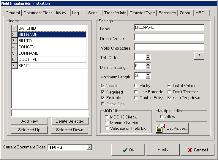
Configuring the Index Tab
To configure the Index tab, perform the following steps to create and configure each Index Field for the selected Document Class:
1. Select a Document Class from the Current Document Class drop down.
2. Type the name of your Index Field in the box directly above the Add New button.
Click the Add New button.
3. The Field name is added to the Index box.
It also is displayed in the Label box in the Settings group box.
4. To enable the Multiple feature in Field Imaging, select the Allow check box in the Multiple Indices group box.
If this option is checked the Multiple button will be visible to Field Imaging users.
The Multiple feature allows Users to apply different sets of Index values for a single Document.
The user can enter a set of values and click the Multiple button to add another set of values for the same Document.
The user repeats this until all sets of values have been entered for a Document.
When the user finishes indexing the batch, Field Imaging makes a copy of the Document for each set of index values entered using the Multiple button.
5. In the Settings area, define the properties of the Index Field that you are configuring.
To begin, in the Label box, type the field’s label as it should appear to Field Imaging Users.
6. If a predetermined value should be entered in the field automatically, type that value in the Default Value box.
Note:Field Imaging Users will be able to overwrite this default value if the Editable check box is also selected.
There are five masks available that will insert system-defined values when the field appears in Field Imaging.
When configuring the Index tab, these masks can be viewed for reference by clicking the ? button, located to the right of the Default Value box.
The masks are:
| Mask | Description |
|---|---|
| [DT:mmddyyyy] | Date mask |
| [DB:###] | Daily Batch sequence number that resets to 0 each day (0-filled to number of #s) |
| [RB:####] | Rolling Batch sequence number that resets when reaching the maximum value |
| [AC] | Agent Code entered on the General tab |
| [SB] |
Scanner Brightness as configured in the scanner’s settings
|
7. If Field Imaging Users should be able to enter only certain characters for this field, type those characters in the Valid Characters box, separated by commas.
8. Field Imaging Users can press the [Tab] key to quickly move the cursor from one field to the next.
The sequence through which the cursor moves is determined by each field’s tab order setting.
In the Tab Order box, enter the position in the tab sequence for this field.
Either click the arrow buttons to enter the tab order number, or type the desired number in the box.
9. In the Minimum Length box, enter the minimum number of characters that the user must enter for this field.
Either type the number in the box, or click the arrow buttons to adjust the number.
The default value is 0, meaning that there is no minimum length requirement.
If you entered a mask in the Valid Characters box, you should leave the minimum length at 0 to avoid conflicting with the mask format.
10. In the Maximum Length box, enter the maximum number of characters that the user can enter for this field.
Either type the number in the box, or click the arrow buttons to adjust the number.
The default value is 0, meaning that there is no maximum number of characters allowed.
If you entered a mask in the Valid Characters box, you should leave the maximum length at 0 to avoid conflicting with the mask format.
11. Mod 10 is an algorithm used to validate number strings.
In the MOD 10 area are check boxes allowing you to apply Mod 10 functionality to the Index Field’s value.
To activate Mod 10 validation for this Index Field, select the MOD 10 Check check box.
12. If Mod 10 validation is activated, and the number entered is not valid, the user can be given the ability to override the failed Mod 10 check.
To enable this feature, select the Manual Override check box.
If a number fails Mod 10 validation, the user is given the option of re-entering the number or overriding the Mod 10 check.
13. By default, Field Imaging validates Index Fields when the user submits their index entries for a Document.
If desired, you can instead have Field Imaging validate a Mod 10 field immediately when the user moves the cursor to another field.
To activate this automatic validation, select the Validate on Field Exit check box.
14. The bottom portion of the Settings area contains a list of check boxes used to enable or disable options for the Index Field.
Select the check boxes for the options that you wish to enable for this field.
The options are:
| Option | Description |
|---|---|
| Visible |
If selected, the user is able to view the field. This option is automatically selected and disabled if either the Required or Editable options are selected. |
| Required |
If selected, the Index Field is required. If selected, the Read Only option is disabled and the Visible option is selected and disabled. |
| Editable |
If selected, the Index Field can be modified by the user. If selected, the Read Only option is disabled and the Visible option is selected and disabled. |
| Read Only |
If selected, the Index Field is read-only. This option is automatically disabled if either the Required or Editable options are selected. |
| Sticky |
If selected, the system automatically assigns this field’s value to the value set on the previous page. |
|
Use Barcode |
If selected, the Index Field’s default value is read from the document’s bar code. The value can be changed if the Editable check box is selected. |
|
Double Entry |
If selected, the user is forced to type the index value twice, and both values must match in order to pass validation. |
|
List of Values |
If selected, the list of available values for the Index Field is loaded into the system. These values are then presented in a drop down list. The values are defined in the Field Items List window when you click the List Values button. |
|
Don’t Transfer |
If selected, the Index Field is not transferred to the corporate imaging system. |
|
Auto Drop-down |
If selected, a list of values opens in a drop down when the user tabs into the Field or clicks in the Field. The values are configured when you select the List of Values check box and click the List Values button. |
15. Configure the remaining Index Fields as needed.
16. You can change the order the Index Fields appear in the Index box and also in the Field Imaging application by selecting a Field in the Index box and clicking on the Selected Up or Selected Down button until the Index Field is in the desired position.
Repeat this until all Fields are in the desired order.
17. You can delete an Index Field by selecting it in the Index box and clicking the Delete Selected button.
Warning: Be careful when using the Delete Selected button because no confirmation message box will open prior to deleting the Field.
18. When you have finished configuring the Index tab, either click the Apply button to save your changes and click the next tab that you wish to configure, or click OK to save your changes and close the Field Imaging Administration dialog box and return to the main Field Imaging interface.
Log Settings
This section explains how to configure logging settings for the Field Imaging installation via the Log tab.
These settings include the Log file directory, days to keep log files, and the logging level.
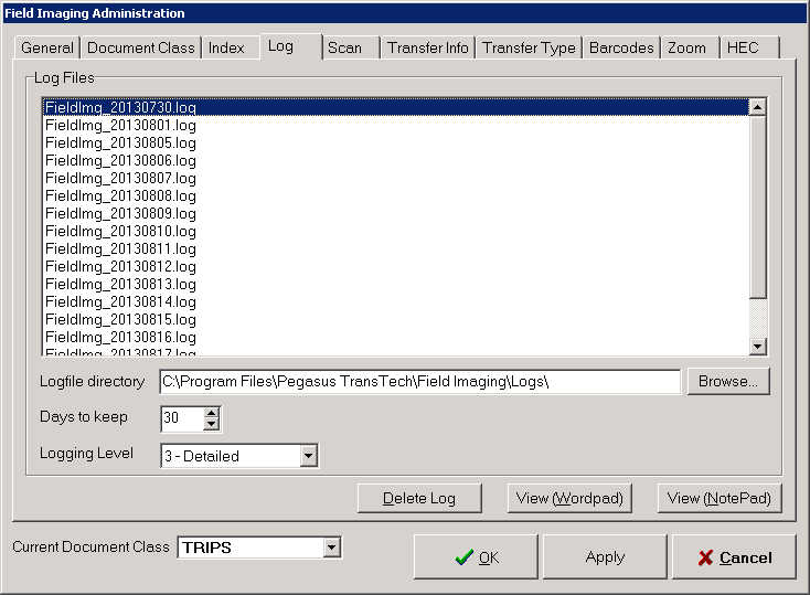
Configure the Log Tab
The Log tab is used both to configure event logging for Field Imaging and to view the log files that have been created.
Instructions for setting up event logging and for viewing log files are presented separately below.
When you have finished configuring the Log tab, either click the Apply button and click the next tab that you wish to configure, or click OK to save your changes, close the Field Imaging Administration dialog box and return to the main Field Imaging interface.
Configure File Logging
1. In the Logfile directory box, enter the complete path of the directory where event log files should be created.
To do this, either type the path in the box, or click the Browse button and navigate to the desired folder.
2. In the Days to keep box, enter the number of days that a log file should be preserved before being purged.
To do this, either type the desired number of days in the box, or click the appropriate arrow button to adjust the number up or down.
The default number of days to keep a log file is 30.
The recommended number of days is 14.
3. Select a log level from the Logging Level drop down.
The available log levels are:
-
- NoLogging
-
- ErrorsOnly
-
- Errors andWarnings
-
-Detailed
-
-Trace
View Log Files
To view log files:
1. Currently saved log files are listed in the Log Files box.
To view a log file, locate the file’s name in the Log Files box, and then click the name to select it.
2. You have the option of viewing the log file using either the Windows WordPad or Notepad utilities.
Click either the View (Wordpad) button or View (NotePad) button to view the log file with the desired utility.
Delete Log Files
Each log file is automatically deleted once its “days to keep” threshold has been met.
However, you can manually delete any log file before its threshold has passed.
To do this:
1. Click the desired file’s name in the Log Filesbox.
2. Click the Delete Log button, and click Yes when prompted to confirm the deletion.
Scanning Settings
This chapter explains how to configure the scanner that will be used by Field Imaging.
This is done via the Scan tab.
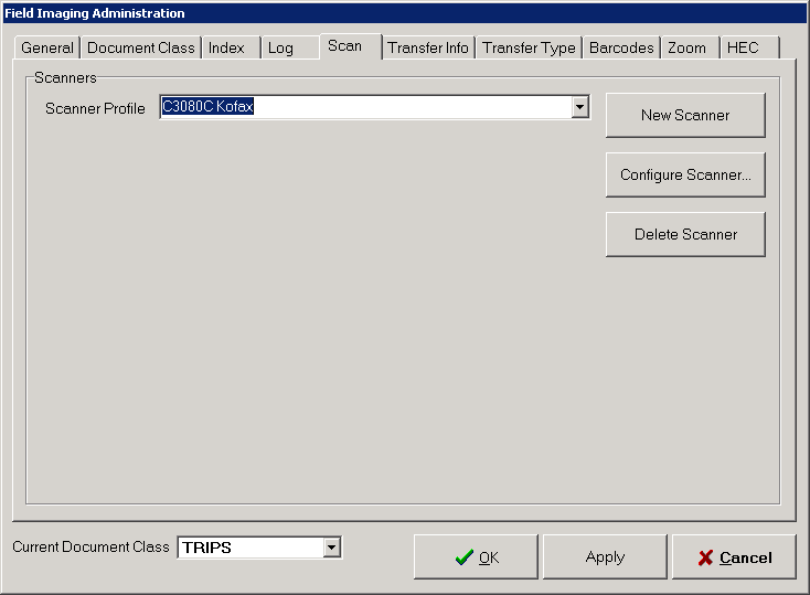
Configuring the Scan Tab
Using the Scan tab, you can create a scanner profile and configure its settings, or edit the settings of an existing scanner profile.
To do this:
1. If you are creating a new scanner profile, click the New Scanner button and proceed to the next step below.
or -
If you are editing an existing scanner profile, expand the Scanner Profile drop down, click the profile that you wish to edit, and proceed to Step 4.
2. When you click the New Scanner button, the New Scanner dialog box appears.
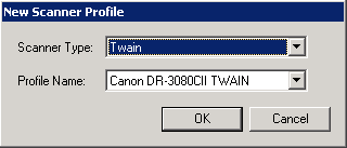
In the Scanner Type drop down, select the type of scanning or input method that the scanner profile will use.
The available choices are:
-
Twain - You will scan using the scanner’s compatible Twain driver
-
Kofax - You will scan using Kofax VirtualReScan (VRS) software
3. In the Profile Name box, type a name for this scanner profile.
When you have finished configuring the New Scanner dialog box, click OK.
4. Click the Configure Scanner button.
The dialog box that appears next is determined by which scanning method was selected for the scanner profile.
-
If the Twain method is being used, the Scanner Configuration dialog box appears. SeeConfiguring TWAIN Scanning below.
-
If the Kofax method is being used, the Kofax Scanner Configuration dialog box appears. See Configuring Kofax Scanning below.
Note: If these dialog boxes do not open on a Windows 7 x64 machine, remove the read-only restriction on the Kofax folder and on all its files and sub-folders.
Configuring TWAIN Scanning
When the TWAIN scanning method is selected and the Configure Scanner button is clicked, the Scanner Configuration dialog box appears with the TWAIN scanner profile in the Select a Scanner to Configure drop down.
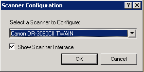
To configure an TWAIN driver for the scanner:
1. Select the TWAIN Scanner from the Select a Scanner to Configure drop down.
2. Select the Show Scanner Interface check box.
Click OK to close the Scanner Configuration dialog box.
3. Click OK to close the Field Imaging Administration window.
You may need to restart Field Imaging.
4. Place a test page in your Twain Scanner and click the Begin Scan button on the main Field Imaging window.
5. The TWAIN Driver window opens.
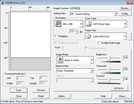
6. Adjust the settings as needed to produce a clear image of the page you scanned.
7. Click the Close button to save your settings.
8. Click the Admin button on the Field Imaging main window.
9. Click the Scan tab and navigate to the Scanner Configuration dialog box.
10. Un-check the Show Scanner Interface check box.
Click OK to close the Scanner Configuration dialog box.
Note: If you are configuring the Canon DR-2050C scanner to use TWAIN and your Field Imaging is installed on Windows XP, you may get the error, Cannot scan documents: Cannot set value of capability.
If this happens use the Kofax driver instead.
Configuring Kofax Scanning
When the Kofax scanning method is selected and the Configure Scanner button is clicked, the Kofax Scanner Configuration dialog box opens.
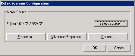
To configure Kofax VRS to control the scanner:
1. To configure basic properties for the source profile, click the Properties button.
The Scanner Properties dialog box opens.
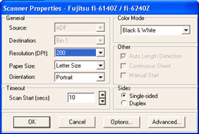
Make sure the Resolution (DPI) is set to “200” and the Color Mode is set to “Black & White”.
Change the other settings to you preferences.
The screen print above shows the typical configuration.
When you have finished configuring the Source Properties dialog box, click OK.
2. To configure advanced properties for the Kofax scanner, click the Advanced Properties button on the Kofax Scanner Configuration dialog box.
The Virtual ReScan Interactive Viewer window opens.
You can fine tune your scanner with the utilities on this window.
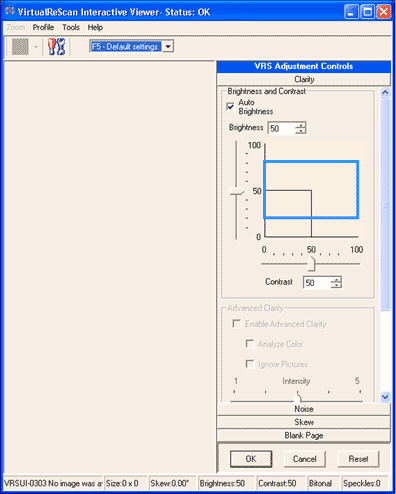
Note: None of the configurable advanced source properties are relevant to the configuration of the Field Imaging scanner, so it is not necessary to click the Advanced Properties button or configure any advanced properties.
Click OK to save your changes and close the Virtual ReScan Interactive Viewer window.
3. To configure Source properties for the Kofax scanner, click the Options... button on the Kofax Scanner Configuration dialog box.
Although it is not necessary, you can modify the settings in this dialog box to detect the front page of two- sided printing and set the default rotation.
You can also configure how sensitive you want to make blank page detection in this window.
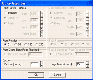
4. When you have finished configuring a Kofax driver for the scanner, click OK to close the Source Properties dialog box.
5. When you have finished configuring the Scan tab, either click the Apply button to save your changes and click the next tab that you wish to configure, or click OK to save your changes and close the Field Imaging Administration dialog box and return to the main Field Imaging interface.
Transfer Settings
This topic explains how to configure the indexed images that will be transferred to the imaging system and the method by which they will be transferred.
These configuration tasks are performed via the Transfer Info and Transfer Type tabs, respectively.
Configuring the Transfer Info Tab
To configure the Transfer Info tab:
1. If the transfer of images should begin immediately when the TRANSFLO® Remote Transfer application is started, select the Auto-start check box.
If the check box is not selected, Remote Transfer will not begin transferring images until a user starts the process.
![]()
2. If the Remote Transfer application should automatically be closed when it has finished transferring images, select the Auto-stop check box.
Note:Backup FTP configured on the Transfer Type tab will not work if the Auto-stop check box is selected.
3. In the Max Batches Per File box, enter the largest number of Batches that should be transferred in each file.
Either type the desired number in the box, or click the arrow buttons to adjust the number up or down.
The default number of Batches is 3.
4. Optional: If desired, each batch can be transferred in its own file.
To enable this function, in the Transferring By Batch area, select the Transfer by Batch check box.
Next, expand the corresponding drop down, and click the name of the Index Field that contains the Batch ID.
In the Batch File Directory box, either type the complete path of the folder where the batch files should be written, or click the Browse button and navigate to the desired folder.
5. If Batches are not being transferred individually (i.e., the Transfer by Batch check box is not selected) they will be transferred by Send Flag.
For this feature to work you must create an additional Index Field on the Index tab named SEND and it must have a Default Value of YES.
The Required and Visible check boxes must be selected and all other check boxes must not be selected.
When Remote Transfer detects a Document with SEND=YES it transfers the Document and sets SEND=NO.
You can define the maximum number of Documents that can be transferred in each batch.
To do this, either type the desired number in the Max Images Per Batch box, or click the arrow buttons to adjust the number up or down.
The default maximum number of images per batch is 20.
6. When you have finished configuring the Transfer Info tab, either click the next tab that you wish to configure (most likely the Transfer Type tab), or click OK to close the Field Imaging Administration dialog box and return to the main Field Imaging interface.
Note: If you have multiple Document Classes configured, Remote Transfer will send all pending Documents from all Document Classes at the same time.
Configuring the Transfer Type Tab
There are two methods of transferring files with Field Imaging.
Files being sent to a remote location can be transferred via FTP.
For files being transferred within a local network, files can be copied directly to a folder on the network.
To configure the Transfer Type tab, begin by selecting a transfer method.
-
To transfer files to a remote location, select the FTP option, and follow the instructions in Configuring TWAIN Scanning below.
-
To transfer files to a location on the local network, select the Direct Copy option, and proceed to the section Configuring Kofax Scanning.
Configuring FTP Transfers
To configure Field Imaging to transfer files via FTP:
1. In the Transfer Method group box, select the FTP radio button if it is not already selected.
![]()
2. If desired, each file can begin being copied to the FTP server with a temporary file extension, and then be renamed once the copy is complete.
This allows the entire file to be transferred before an application attempts to process it.
To enable this feature, select the Use FTP Rename check box.
3. Field Imaging provides the option of using a backup FTP server if the primary server is not available.
To enable this function, select the Enable Backup FTP check box.
In the box provided, enter the number of times that Field Imaging should attempt to connect to the primary FTP server before it switches to the backup server.
Either type the desired number of attempts in the box, or click the arrow buttons to adjust the number up or down.
The default number attempts is 1.
4. In the Primary FTP Information group box, enter the information that Field Imaging should use to connect to the primary FTP server.
-
In the Server box, type the address of the primary FTP server.
-
In the User Name box, type the ID that should be used to log into the server.
-
In the Password box, type the password for the login ID.
-
In the Directory box, type the path on the FTP server where Field Imaging should place the transferred files.
-
If desired, Field Imaging can automatically dial a Microsoft Remote Access Service (RAS) connection that has been configured on the local computer.
To enable this option, select the Auto-dial check box, and type the name of the desired RAS connection in the box provided.
5. If the Enable Backup FTP check box was selected, configure the settings in the Backup FTP Information area, following the same instructions provided above for the primary FTP connection settings.
6. When you have finished configuring the Transfer Type tab, either click the Apply button to save your changes and click the next tab that you wish to configure, or click OK to save you changes and close the Field Imaging Administration dialog box and return to the main Field Imaging interface.
Important: Documents will be saved on the FTP server in a sub-directory for each Document Class of the directory configured in the Directory box, with the Document Class name as the sub-directory name. Each directory must be created manually and must match the Document Class name exactly.
Configuring Direct Copy Transfers
To configure Field Imaging to transfer files to another location on the local network:
1. In the Transfer Method area, select the Direct Copy option.
![]()
2. In the Directory box, enter the path of the local folder where the transferred files should be placed.
Either type the full UNC path of the folder, or click the Browse button and navigate to the desired folder.
Note: If configuring the Directory path and using a network path by copying and pasting or typing in the path into the Directory box and the logged in user does not have access to the path, Field Imaging may appear to be locked up as it goes out and verifies access.
If you type [Alt] + [Tab] on your keyboard you will see that there is a message box behind the Field Imaging window awaiting user input to access and/or create the network path.
3. When you have finished configuring the Transfer Type tab, either click the Apply button to save your changes and click the next tab that you wish to configure, or click OK to save you changes and close the Field Imaging Administration dialog box and return to the main Field Imaging interface.
Configure Barcode OCR and Document Magnification Settings
This topic explains how to configure the Optical Character Recognition (OCR) parameters that Field Imaging will use to recognize and apply bar code data.
These properties are defined via the Barcodes tab.
The topic also provides instructions for configuring the Zoom tab, which allows you to define how the document view magnification function behaves for Field Imaging Users.
Configuring the Barcodes Tab
Via the Barcodes tab, bar codes are associated with Index Fields.
Before this can be done, though, bar code profiles must be created and OCR settings must be defined.
Creating and Editing Barcode Profiles
To create or edit a bar code profile:
1. Click the Configure button.
![]()
2. The Pegasus TransTech Barcode Configuration window opens.
Using this window, you must select the bar code whose value will be assigned to the selected Index Field.
![]()
To create a bar code profile, continue to the next step.
To edit a bar code profile, click the bar code’s name in the Bar Code List box, and skip ahead to Step 4.
3. To add a new bar code to the Bar Code List box, click the Add button.
Type a name for the new bar code in the New Bar Code dialog box, and click OK.
![]()
4. In the Name box, type a new name for the bar code, if necessary.
When you are finished configuring the bar code and click OK, the bar code’s name will be updated in the Bar Code List box.
5. In the Min Length box, either type the minimum number of characters that the bar code must have, or click the arrow buttons to adjust the number up or down.
The default value of 0 means that there is no minimum number of characters that the bar code must have in order to be recognized by Field Imaging.
6. In the Max Length box, either type the maximum number of characters that the bar code can have, or click the arrow buttons to adjust the number up or down.
The default value of 0 means that there is no maximum number of characters that the bar code can exceed that will cause Field Imaging not to recognize it.
7. In the Granularity box, enter the number of lines that should be skipped between passes while attempting to recognize a bar code.
Either type a number in the box, or click the arrow buttons to adjust the number up or down.
A lower number yields a more thorough recognition, but a slower read.
A higher number will improve read times, but may yield a lower recognition rate.
The default granularity setting is 9 lines.
8. If multiple bar codes will appear on a single page and you wish to differentiate among bar codes by their prefixes, select the Use Barcode Prefix check box.
![]()
In the box that appears, type the prefix that distinguishes the desired bar code.
This prefix is not case sensitive.
Note: If this option is selected, the Position Sensitive option cannot be used.
9. In the Code Types area, select the check boxes corresponding to the types of bar codes that Field Imaging should recognize for the selected Index Field.
These code types are defined in the table below.
| Code Type | Definition |
|---|---|
| Code 128 |
Code 128 is a bar code standard that is used for several applications and is also referred to as ISBT 128, UCC-128, EAN-128 and USS Code 128. Code 128 is a very high density alphanumeric bar code. Each data character encoded in a Code 128 symbol is made up of 11 black or white modules. The stop character, however, is made up of 13 modules. Three bars and three spaces are formed out of these 11 modules. Bar and spaces can vary between 1 and 4 modules wide. The symbol includes a quiet zone (10x dimensions), a start character, the encoded data, a check character, the stop character, and a trailing quiet zone (10x dimensions). |
| EAN-13 |
EAN-13 is used world-wide for marking retail goods. The EANsymbol encodes 13 characters: the first two or three are a country code which identify the country in which the manufacturer is registered (not necessarily where the product is actually made). The country code is followed by 9 or 10 data digits (depending on the length of the country code) and a single digit checksum. 2-digit and 5-digit supplemental bar codes may be added for a total of 14 or 17 data digits. |
| UPCA |
UPC-A is used for marking products which are sold at retail in the USA. The bar code identifies the manufacturer and specific product so point- of- sale cash register systems can automatically look up the price. UPCA encodes 12 numeric digits. The first digit identifies the numbering system being used. The next group of 5 digits identifies the manufacturer. |
|
Interleaved 2 of 5 |
Interleaved 2 of 5 is a numbers-only bar code. The symbol can be as long as necessary to store the encoded data. The code is a high- density code that can hold up to 18 digits per inch when printed using a 7.5 mil X dimension. There are five bars, two of which are wide, and five spaces, two of which are wide. The symbol includes a quiet zone, the start character (narrow bar-narrow space-narrow bar-narrow space), the encoded data, the stop character (widebar-narrow space- narrow bar), and a trailing quiet zone. |
| Code 39 |
Code 39 is an easy to use alpha-numeric bar code. It is also commonly called LOGMARS, Code 3 of 9 or the 3 of 9 Code. Code 39 is an alphanumeric bar code. The symbol can be as long as necessary to store the encoded data. It is designed to encode 26 uppercase letters, 10 digits and 7 special characters. It can be extended to code all 128 ASCII characters by using a two character coding scheme. Each data character encoded in a Code 39 symbol is made up of 5 bars and 4 spaces for a total of 9 elements. Each bar or space is either "wide" or "narrow" and 3 out of the 9 elements are always wide. |
| EAN 8 |
EAN-8 is a shortened version of the EAN-13 code. It includes a 2- or 3- digit country code, 4 of 5 data digits (depending on the length of the country code), and a checksum digit. While it is possible to add a 2- digit or 5-digit extension bar code, the primary purpose of the EAN-8 code is to use as little space as possible. The data digits in an EAN-8 symbol specifically identify a particular product and manufacturer. |
| UPCE |
UPC-E is a variation of the UPC-A symbol that is used for number system 0. By suppressing zeroes, UPC-E codes can be printed in a very small space and are used for labeling small items. Only bar codes containing zeroes are candidates for the UPC-E symbol. |
10. If multiple bar codes will appear on a single page and you wish to differentiate among bar codes by their position on the page, select the Position Sensitive check box.
![]()
In the BarCode Position On Page area that appears, enter the horizontal and vertical coordinates of the center of the desired bar code in the X Axis and Y Axis boxes, respectively.
You can type the coordinates in the boxes provided if desired, but the easier route is to click the position on a sample image of the document to be read.
To do this, you must have a scanned image of the type of document to be scanned saved on the local network.
Click the Use Sample Image button, and navigate to and select the sample image via the Open dialog box.
The sample image is displayed.
Position the mouse pointer over the center of the desired bar code and click.
The image closes and the coordinates you clicked appear in the X Axis and Y Axis boxes.
11. When you have finished configuring the OCR settings for the bar code tobe associated with the selected Index Field, click OK to close the Pegasus TransTech Barcode Configurationwindow.
Note: If any of the selected bar code criteria are not met for a given document, no value will be assigned to the Index Field for that document, and the field will have to be manually indexed by a Field Imaging User.
Assigning Barcodes to Indexing Fields
To assign a bar code profile to an Index Field:
1. In the Index Fields box, click the name of the Index Field to which you will associate a bar code.
Note: If the field for which you are looking does not appear in the Index Fields box, it means that the Use Barcodes check box has not been selected for that field on theIndex tab.
2. In the Bar Code Info area, expand the Bar Code Name drop down.
In the list, click the name of the bar code profile that should be associated with the Index Field.
3. The Use Entire Bar Code check box is selected by default.
If all of the data stored in the bar code should be assigned as the value of the Index Field, leave this check box selected.
If, however, only part of the barcode’s value should be used, clear the Use Entire Bar Code check box.
![]()
In the Bar Code Start Position box, enter the first character that should be read when determining the Index Field’s value.
Either type the number in the box or click the arrow buttons to adjust the number up or down.
The default value is 1, meaning that Field Imaging will start reading the Index Field’s value with the first character in the bar code.
In the same way, enter the final character to be read in the Bar Code End Position box.
The default value is 0, meaning that no end character is defined.
Field Imaging will read through the final character in the bar code.
4. If you have multiple Index Fields to which to assign bar code profiles, click the name of the next field and select a bar code profile in the same manner as described above.
Note: If a document has multiple bar codes for an Index Field, it would only display the data for the last valid bar code for that Index Field.
It is not recommended to set more than one bar code for an Index Field.
5. When all Index Fields have been assigned bar code profiles, either click the Apply button to save your changes and click the next tab that you wish to configure, or click OK to save your changes and close the Field Imaging Administration window and return to the main Field Imaging interface.
Configuring the Zoom Tab
To configure the Zoom tab:
1. In the ImageZoom% box, enter the percent by which images should be zoomed when a Field Imaging user is using the magnifying glass tool.
Either type the desired percentage in the box, or click the arrow buttons to adjust the percentage up or down.
The available values are 1-1000.
The default value is 200.
Note: This setting does not have an effect when the Rubber Band magnification method is used.
It applies only to the Magnifying Glass method.
![]()
2. In the ButtonZoom% box, enter the percent by which images should be zoomed when a Field Imaging user clicks the Zoom button.
Either type the desired percentage in the box, or click the arrow buttons to adjust the percentage up or down.
The available values are 1-1000.
The default value is 200.
3. Optional: A sequence of zoom points can be assigned so that each time the Field Imaging User clicks the Zoom button, a different area of the displayed document will be zoomed.
To use this feature, begin by entering the desired number of zoom points in the Number of Points box.
Either type the desired number, or click the arrow buttons to adjust the number up or down.
The default value is 0, meaning that the zoom points feature will be disabled.
Next, assign coordinates to the zoom points to be used.
To begin, click the arrow button next to the Point Number list box to expand the list, and click 1 to select the first zoom point.
Place a document like the ones to be scanned in the scanner, and click the Scan Sample button.
On the scanned image that appears, click in the center of the area that should be zoomed.
The coordinates that you clicked now appear in the Zoom Point box.
Note: You cannot type zoom point coordinates directly in the Zoom Point box.
They must be entered by clicking a scanned sample document.
If you are assigning multiple zoom points, click the next point in the Number of Points list box and configure it as described in this step.
Continue configuring zoom points until all zoom point coordinates have been established.
4. In the Default Zoom Type area, select which zoom method should be the default for Field Imaging Users:
-
Rubber Band (default) - Users can click drag a rectangle around the area to be zoomed.
-
Magnifying Glass - Users can click the spot on the document that they wish to zoom, and the area will be zoomed by the percentage entered in the Image Zoom % box.
5. When you have finished configuring the Zoom tab, either click the Apply button to save your changes and click the next tab that you wish to configure, or click OK to save your changes and close the Field Imaging Administration window and return to the main Field Imaging interface.
Host-Enabled Component Settings
Introduction
The HEC tab is used to establish settings for the Host-Enabled Component (HEC), installed under the name TRANSFLO® Index Validation.
If using HEC with Field Imaging, the script to be used can be created via the HEC tab.
Note:TRANSFLO® Index Validation must be installed before you can configure the HEC tab.
Configuring the HEC Tab
To configure the HEC tab:
1. Expand the HEC Script drop down, and click the name of the HEC script that you wish to use with Field Imaging.
If the necessary script is not in the list, you must either create it or edit an existing script.
Click the Edit Scripts button.
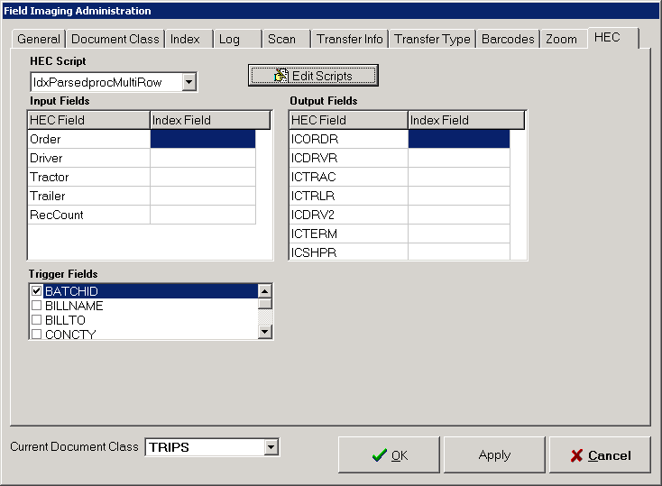
2. Once you have selected a HEC script to use, its fields are populated in the HEC Field columns of the Input Fields and Output Fields tables.
In the Input Fields table, in the Index Field column click in the cell next to the name of the first HEC field that will supply an input value.
A list of the available Index Fields appears.
Click the name of the Index Field that should receive its value from the associated HEC field.
Continue matching Index Fields with HEC fields as necessary.
3. In the Trigger Fields box, select the check box for each Index Field that should act as a trigger for an Index Validation call.
When a trigger field is encountered by Field Imaging, the HEC script will be run and will return values for the Index Fields defined in the Input Fields table.
4. Configure the Output Fields table in the same fashion as the Input Fields table.
For each HEC field matched with an Index Field, an output value will be sent to Index Validation.
Note:HEC activities occur prior to a Document being scanned.
Therefore, a bar code cannot be used as the source of a HEC output value.
5. When you have finished configuring the HEC tab, either click the Apply button to save your changes and click the next tab that you wish to configure, or click OK to save your changes and close the Field Imaging Administration window and return to the main Field Imaging interface.
Note: If an Index Field is configured with a Maximum Length less than the length of the text string returned by HEC, HEC does not truncate the return value to the Maximum Length configured on the Index tab.
The entire text string returned by HEC populates the Field.