Transflo DMS Workflow Studio
TRANSFLO® Workflow Studio is a powerful tool that can be used to model any business process in your organization. It contains tools to create forms, define data elements and tie these to your processes. With minimal code a process model can be tested and deployed throughout your organization.
This topic describes the basic elements of a Workflow Studio Project. You can create a project and process and then add Fields, Parameters, Participants, Processes and Forms to it.
Included with your installation CD are sample processes that you can use as templates to model your own processes. TRANSFLO® Workflow Studio can be installed on your desktop or laptop computer. You don’t have to be connected to your corporate network to model a process. When you are ready to deploy your process, you can connect to your network and publish it.
RAM
-
Minimum RAM: 512 MB.
-
Recommended: 1.0 GB or higher
Hard Drive
-
Minimum Available Hard Drive Space: 725 MB.
-
Recommended: 2.0 GB
Operating System Requirements
-
Windows Server 2003 R2 SP2
-
MS04-012: Cumulative Update for Microsoft RPC/DCOM (KB828741).
-
Windows Server 2008 (x86 and x64)
-
Windows 7, 10, or 11 (x86 and x64)
To create a Workflow Project do the following:
-
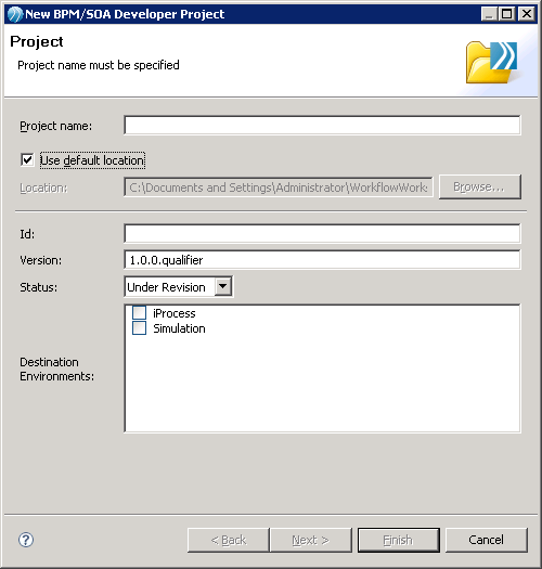
On the menu bar select File > New > BPM/SOA Developer Project. The New BPM/SOA Developer Project window opens.
-
In the Project name field, enter a name for your project. This will create a project in the default workspace location
-
(Optional) To create a project in a different location deselect the Use default location check box and type a path in the Location text box or use the Browse button to select a different location.
-
Enter a version in the Version field using the convention,
<major>.<minor>.<micro>.<qualifier>
where,
<major> is incremented when the new version is incompatible with the previous version.
<minor> indicates a compatible revision.
<micro> indicates an internal change.
<qualifier> is used to identify unique builds. You may use a date time format or another convention. Consult with your project manager to establish a common practice.
5. Select a life cycle status from the Status drop down.
This is for informational purposes only and generally is used as follows:
-
Under revision - for packages in development
-
Under test - for packages in User Acceptance Testing (UAT)
-
Released - for packages in production
6. (Optional) Select the intended run-time environment for the project in the Destination Environments box.
For processes the following validation occurs:
-
If you select iProcess, processes created under this project will be validated for direct deployment to the Workflow Engine.
-
If you select Simulation, processes created under this project will be validated for simulation in Workflow Studio as well as for Business Process Modeling Notation (BPMN) correctness.
-
If you do not select a destination environment, only basic BPMN validation will be performed.
Click Finish.
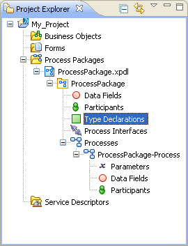
8. A Workflow Project is created in the Project Explorer with place holders where you will create Forms, Data Fields, Participants, Processes etc.
Under Process Packages a Process Package is created for you in the form of an XPDL file. (XPDL is a standard Process modeling file format and stands for XML Process Definition Language.)
A Process is started for you as well with placeholders for Parameters, Data Fields and Participants.
Process modeling is at the core of using Workflow to analyze and improve your business. You create a process, also called a procedure, where you model your business process.
Three (3) approaches for modeling a process are given below:
-
Create a visual representation of your model with placeholders for tasks, decisions and flows. In this approach you decide which tasks will be automated, which will be manual after the entire process is mapped out and analysis has been completed. This approach is a good practice when you are modeling a new process or an existing process that has not been well defined or needs to be modified significantly.
-
Create a model and, as you go, decide if your task is manual or automated. If the step is automated you decide what type of automation will be used. This is usually used if your process has been well defined or you are replicating a Procedure from an older version of Staffware.
-
Use a template and modify it to capture the needs of your organization. Templates often contain the best practices for the type of Process they represent and only need to be modified slightly to align with your business process.
In the following example steps, you will be creating a simple Hiring Process using a combination of the first two approaches listed above.
When modeling an existing process keep in mind that this is an opportunity to refine your process. If something did not work well in the past, this is your opportunity to improve. Once a process has been created and deployed, you can measure its effectiveness and refine it where needed. This real world analysis and adaptation is one of the most powerful uses of the TRANSFLO® Workflow Studio.
To create a process, follow these steps:
-
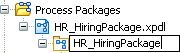
Rename your Process Package with a more meaningful name.
-
Select the XPDL file name in the Project.
-
In the File menu, choose Rename... and enter a new file name.
-
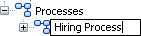
Repeat these sub-steps to rename your processes in each package.
-
-
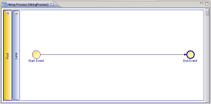
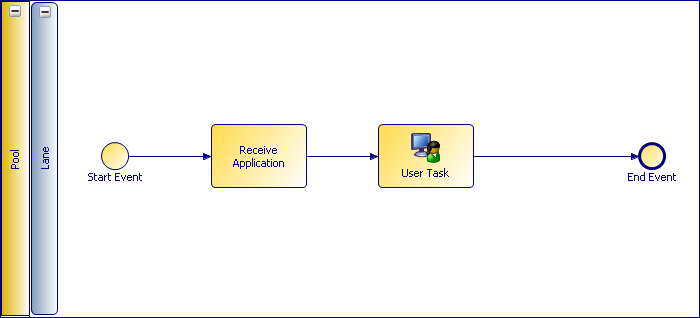
Double-click on the Process name you created. The Process opens in the Main Editor. Notice that the Process already has a Start Event and an End Event that are connected by a Sequence Flow arrow.

-
In the Properties View click on the Advanced tab.

-
Select “false” from the Use Working Days drop-down.
-
The Use Working Days option specifies whether to use the iProcess Engine's working week or a full 7-day week. Selecting “true” excludes weekends when performing date calculations such as checking for deadline expiry. By default, this option is set to “true” so the working week is used.
-
You can define the Use Working Days option for a procedure or sub-procedure. You must have a single procedure object selected. You cannot define this flag for multiple objects in the same operation.
-
-
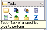
If the Palette is not already visible expand it so that it is visible. Click
 .
. -
Click Tasks to expand the Tasks group of options represented by icons.
-
The table below describes all of these Task types and how they were represented in TRANSFLO® Workflow version 4.0 and earlier.

| TRANSFLO® Workflow 4.0 | TRANSFLO® 2012 Workflow Studio | Description | |
|---|---|---|---|
|
|
Complex Router |
|
A generic Task is often used when designing a Process before it has determined if the task will be automated or not. A generic Task can have multiple inputs and multiple outputs. A generic Task is one possible translation of a Complex Router in previous versions of Workflow. |
|
|
User Step |
|
Either the User or Manual Tasks can be used to represent a task performed by a person. It is strongly recommended that you use a User Task since a Manual Task does not accept Parameters and does not provide any fields on the form. User or Manual Tasks represent User Steps in previous versions of Workflow. |
|
|
EAI |
|
Use a Service Task to for the following; Web Services, Java, Database, E-Mail, BW Service. Use a Script Task for all other scripting tasks. Service Tasks and Scripting Tasks correspond to EAI Steps in previous versions of Workflow. A list of iProcess System Values that can be used in your Workflow Studio scripts is included below in this article. |
|
N/A |
|
A Send Task is used to wait for a message from an external participant. Send Tasks are used to send messages to a system or person outside of the process (often using a web service) and can be paired with Receive Tasks. |
|
|
|
Event |
|
A Receive Task is used to wait for a message from an external participant. A Receive Task must be used when there is no inbound flow, when you require a normal and deadline outbound flows, or when you do not want to withdraw the event step. A Receive Task corresponds to an Event step |
|
N/A |
|
A Reference Task is used to re-use all attributes of a task or sub-process defined elsewhere. A Reference Task refers to another task and prevents you from having to duplicate the same task several times in a process. (The reference is set in the General tab of the Properties view.) |
|
|
N/A |
|
The Reusable Sub-Process is used to execute an external sub-process. Reusable Sub-Process can be executed from a different process than the process where it resides. The called process does not have access to data fields and parameters of the calling process and package. For this reason, data mapping must be performed to and from the called process. |
|
|
N/A |
|
The Embedded Sub-Process is used to execute an internal sub-process and has the following characteristics:
|
|

 Task
Task User Task
 Manual Task
 Service Task
 Script Task
 Send Task
 Receive Task
 Reference Task
 Reusable Sub- Process
 Embedded Sub- Process
-
The first step in our Hiring Process will be to receive the applicant’s application.
At this point it is unclear if this task will be performed by a Person or if it will be automated, so a generic task will be used as a place holder for now.
Click on the Task icon and click on the Sequence Flow arrow between the Start Event and the End Event.
The task is placed at this point.
Notice that the Sequence Flow arrow became two Sequence Flows: one from the Start Event to the Task and another from the Task to the End Event.

Tip: The first step in all main TRANSFLO® processes cannot be an interactive step where user intervention is required. The first step will always be released automatically by the case initiation procedure.
-
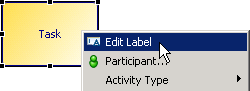
Right-click on the task and choose Edit Label in the menu.

-
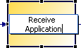
Enter Receive Application and press the Enter key.
12. Once the application is in the system a person must review it.
Click on the User Task icon  in the Palette and click on Sequence Flow arrow between the Receive Application Task and the End Event in your Process to insert a User Task.
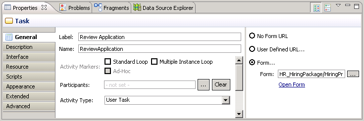
13. Click on the User Task to select it.
Note that the Properties tab changes to show Task properties for the User Task you selected.
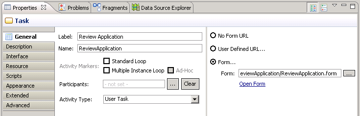
-
In the right pane select a method to associate a form with the User Task.
The three methods are:
-
No Form URL - Select this option if upon export to the Workflow Engine you want to display a standard Workflow form.
-
User Defined URL - Select this option if you want to point to a specific URL to a Web form created outside of Workflow Studio.
If you select this option but do not specify a URL, upon export to the Workflow Engine a standard the Workflow form is created.
-
Form - Use this option if you have created a form using TIBCO Business Studio Forms.
For instructions on how to create forms, see .
-
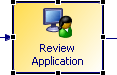
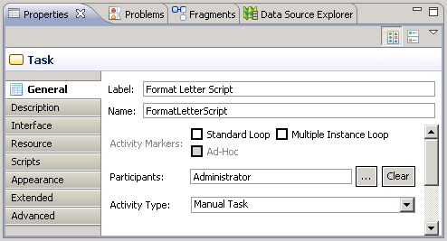
15. In the General properties area change the Name property to “Review Application.”
The name changes on the label of the User Task you selected.
There are 8 end points on the selected Task.
Use these to re-size the Task to your preference.
16. In the Palette click Gateways to expand the Gateway group of activities.
The Exclusive Data-Based Gateway is the most commonly used Gateway.
To see descriptions of any activity in the Palette, point to the icon with your mouse pointer.
Hover-text gives you the activity’s name and a brief description.
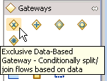
Gateways are used to make decisions when there is more than one possible flow after a task or before a task.
The table below describes Gateway types and how they were represented in TRANSFLO® Workflow version 4.0 and earlier.
|
TRANSFLO® Workflow 4.0 |
TRANSFLO® 2012 Workflow Studio |
Description |
|---|---|---|
|
|
|
The most common use of Exclusive Data-Based Gateway is used to decide between 2 outbound flows. The Conditional Outbound Flow is used as the “true” path and the Default Outbound Flow is used as the “false” path. In this use the Exclusive Data-Based Gateway represents a Condition in previous versions of Workflow. A Exclusive Data-Based Gateway can be used to route to different paths. This is true when none of the outbound flows are Conditional Outbound Flows. In this case Exclusive Data-Based Gateway represents a Complex Router in previous versions of Workflow. |
|
|
|
A Parallel Gateway with multiple inbound flows will prevent the Process flow to proceed past it until all incoming paths have completed. When used this way, a Parallel Gateway is analogous to a Wait step in previous versions of Workflow. A Parallel Gateway that does not have multiple inbound flows but has multiple outbound flows is used to spawn multiple parallel paths. In this case a Parallel Gateway is analogous to a Complex Router in previous versions of Workflow. |
|
N/A |
|
An Exclusive Event-Based Gateway conditionally splits or joins flows based on an event. The sequence flow is chosen based upon an external event (for example, a JMS message). |
|
N/A |
|
An Inclusive Gateway conditionally splits or joins any sequence flows based on data. In an inclusive gateway used for branching, each output Sequence Flow is independently evaluated according to an expression. This means that anywhere from zero to the maximum output sequence flows can be taken. In practice, you should either provide a default sequence flow or ensure that at least one sequence flow evaluates to True. When used to merge flow, any upstream sequence flows are synchronized, but the gateway does not wait for all sequence flows. |
| N/A |
 Complex Gateway Complex Gateway |
A Complex Gateway conditionally splits or joins any sequence flows based on a complex expression. When used as a decision, the expression determines which of the outgoing sequence flow are chosen for the process to continue. When used to merge flow, the expression determines which of the incoming sequence flows is required for the process to continue. |


 Exclusive Data-Based Gateway
 Parallel Gateway
 Exclusive Event- Based Gateway
 Inclusive Gateway
Note: The Activity Type gadget is visible when you select an activity.
Repeatedly clicking on the Activity Type gadget allows you to quickly cycle through the activity types for the group that the activity belongs to.
-
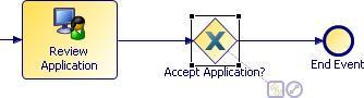
Once the HR User reviews the application, a decision must be made to determine if the applicant merits an interview. Click on the Exclusive Data- Based Gateway in the Palette and click on the Sequence Flow between the Review Application Task and the End Event. In the Properties tab type “Accept Application?” in the Name Property.

-
Add a User Task called “Interview Applicant” between the Accept Application? Exclusive Data-Based Gateway and the End Event in your Process.
-
Click on the Service Task icon in the Task group on the Palette.
Click below the Accept Application? Exclusive Data-Based Gateway to place a Service task on you Process.
Name it “Send Regret Letter.”
-
Click on the Sequence Flow that connects the Accept Application? Exclusive Data-Based Gateway and the Interview Applicant User Task and type the Delete key to remove it.
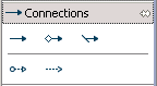
21. In the Palette click on Connections to expand the Connections group of activities.
Note: The Create Connection gadget  is visible when you select an Activity.
Dragging the Create Connection gadget allows you to quickly connect Activities with Sequence Flows.
Connections show the order in which Activities are executed in your Process by connecting these activities together.
The table below describes the available Connection Types in the Connections group and how they were represented in TRANSFLO® Workflow version 4.0 and earlier.
| TRANSFLO® Workflow 4.0 |
TRANSFLO® 2012 Workflow Studio |
Description | |
|---|---|---|---|
|
|
Sequence Flow |
|
The Sequence Flow defines the process flow between objects. This is the most common Connection Type used to connect Activities. This is the same as in previous versions of Workflow. |
|
|
Condition |
|
The Conditional Flow is used to specify the true condition of a Exclusive Data-Based Gateway. The Default Flow is used to specify the false condition of an Exclusive Data-Based Gateway. Conditional Flows and Default Flows correspond to Condition steps in previous versions of Workflow. |
|
N/A |
|
A Message Flow is used to create an asynchronous message flow between objects in different pools or between pools. |
|
|
N/A |
|
An Association either connects flow and non-flow objects or specifies the Compensation task for a Compensation event on a task boundary. |
|

 Sequence Flow
 Conditional Flow
 Default Flow
 Message Flow
 Association
-
Click on the Conditional Flow in the Palette.
On the Process, click on the Accept Application?Exclusive Data-Based Gateway and then on the Interview Applicant User Task.
-
Click on the Default Flow in the Palette.
On the Process, click on the Accept Application?Exclusive Data-Based Gateway and then on the Send Regret Letter Service Task.
-
In the same manner connect the Send Regret LetterService Task to the End Event with a Sequence Flow.

-
In the Project Explorer highlight the XPDL file and on the File Menu select Save All to save your work.
-
If an application has been sitting in the Review Application step too long the Reviewer will need a reminder.
Click the Catch Intermediate Event and Throw Intermediate groups to expand them.
Intermediate Events are used to modify the sequence or timing of activities in a Process.
Catch Intermediate Events wait for an event and Throw Intermediate Events resumes the flow.
The table below describes the types of Intermediate and how they were represented in TRANSFLO® Workflow version 4.0 and earlier.


|
TRANSFLO® Workflow 4.0 |
TRANSFLO® 2012 Workflow Studio |
Description | |
|---|---|---|---|
|
|
Event |
|
The Catch Intermediate Event of Trigger Type: None indicates an unspecified event in the Process. An Intermediate Event may be used when there is one inbound and one normal outbound flow. The Catch Timer Intermediate Event is triggered at a specific time or after a period of time has elapsed. A Catch Timer Intermediate Event may be used when there is one inbound and only a deadline outbound flow. A Catch Timer Intermediate Event can be placed on the boundary of a task to define the deadline for the Task. Intermediate Events and Timer Intermediate Event correspond to Events in previous versions of Workflow. |
|
Withdraw |
|
A Catch Error Intermediate Event is used to catch an exception thrown inside a task or sub-process. Catch Error Intermediate Events that are used to stop Process flow correspond to Withdraw Events in previous versions of Workflow. |
|
|
N/A |
|
Throw/Catch Link Intermediate Events indicate a connection from one or more Throw Link Intermediate Events to a Catch Link Intermediate Event in the same parent process. This can be thought of as a "go to" or "off page connector" that you can use to break up a process for better legibility. |
|
 Catch Intermediate Event
 Catch Timer Intermediate Event
 Catch Error Intermediate Event
 Throw Link Intermediate Event
 Catch Link Intermediate Event
| TRANSFLO® Workflow 4.0 |
TRANSFLO® 2012 Workflow Studio |
Description |
|---|---|---|
|
|
|
Throw/Catch Message Intermediate Events either stop the flow of the process pending the receipt of a message (catch), or send a message and resumes flow (throw). |
|
|
|
|
|
|
Conditional Intermediate Event |
The Catch Conditional Intermediate Event waits for the event when conditions are met. (The event is triggered based on the evaluation of a condition.) |
|
|
|
The Throw Signal Intermediate Event broadcasts a signal. A Throw Signal Intermediate Event is assigned a default signal name (signal n, where n is an incremental number). |
|
|
The Catch Signal Intermediate Event catches a signal. |
|
|
|
|
The Throw Multiple Intermediate Event triggers multiple event types. |
|
|
The Catch Multiple Intermediate Event waits for an event triggered by one of a number of methods. (The Throw/Catch Multiple Intermediate Events indicate that there can be several possible triggers for the event.) |
|
|
|
|
The Throw Compensation Intermediate Event is placed in a sequence flow of the process and throws a call for compensation. |
|
|
The Catch Compensation Intermediate Event is attached to the boundary of an activity, and catches a named compensation call. (Throw/Catch Compensation is used to process compensating activities for previously executed tasks.) |
|
|
|
|
The Catch Cancel Intermediate Event is used on the boundary of a transaction sub-process. It is triggered if a cancel end event is reached within the transaction sub-process or if a transaction protocol “cancel” message is received while the transaction is being performed. |
 Throw Message Intermediate Event
 Catch Message Intermediate Event
 Catch
Catch Throw Signal Intermediate Event
 Catch Signal Intermediate Event
 Throw Multiple Intermediate Event
 Catch Multiple Intermediate Event
 Throw Compensation Intermediate Event
 Catch Compensation Intermediate Event
 Catch Cancel Intermediate Event
-
Select the Timer Intermediate Event from the Palette and click the bottom edge of the Review ApplicationTask in the Hiring Process.
This will attach the Timer Event to the Task.

28. Place a Service Task directly below the Review ApplicationTask and name it “Remind Interviewer.”
29. Connect the Timer Event on the Review Application Task with the Remind InterviewerService Task with a Sequence Flow.
30. Click on the Text Annotation icon in the Palette and click on the Process near the Timer Event on the Review Application Task.
In the General Property:Text in thePropertiestab type the note as it appears below.
Use an Association to show that the annotation refers to the Timer Event.
Note:Text Annotations do not affect the Process functionality. They are used to make the Process easier to understand.
Note: For more information on Workflow Scripting, see the Online Help.
Note: For a list of iProcess System Values that can be used in your Workflow Studio scripts see Appendix A - iProcess System Values.
31. After some analysis, your IT department tells you that your hiring application cases will be triggered by external HR system.
In the case the initial task must be a scripting step.
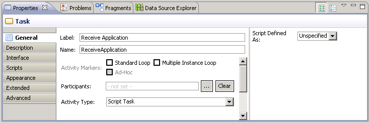
To change the Receive Application task to a scripting task,
-
In the Process tab, highlight the Receive Application task.
-
In the Properties tab, on the General properties menu, change the Activity type to Script Task.
32. Rename the Pool Label by clicking the “Pool” label and typing “HR” in the Name property on the Properties tab.
33. Rename the Lane Label by clicking the “Lane” label and typing “Hiring Process” in the Name property on the Properties tab.
34. Save your work.
There are several ways to group items in your Process.
These groupings are called Artifacts.
Like Annotations they are not intended to affect your Process functionality.
The table below describes the available artifacts.
|
TRANSFLO® 2012 Workflow Studio |
Description |
|---|---|
|
|
Pools are used to group major functionality. Pools can be divided into several Lanes. |
|
|
Lanes can be used to improve the readability of a Process by dividing the Process horizontally and grouping related activities in each Lane. Lanes are similar to Swim Lanes in UML Activity diagrams. |
|
|
Data Objects are used to show how data is required or produced by activities. They are connected to activities through Associations. |
|
|
A Group is drawn around a number of activities that are related. It can be used for documentation or analysis purposes, but does not affect the Sequence Flow. |
|
|
A Text Annotation is used to add text to the diagram to make the process easier to read. Text annotations can be linked to an item on the process with the Association Connection. |
 Pool
Pool Lane
Lane Data Object
 Group
Group Text Annotation
So far you have created a basic Process map for the Hiring Process.
The Process still needs functionality for the automated steps and the decision at the XOR Gateway.
Each User step requires a Form and has to be tied to a Participant.
The information has to be passed along the Process in the form of Parameters and Data Fields.
Parameters are used by Service Tasks.
Define Data Fields
For data to be used in your Process you will need to define Data Fields and Parameters.
A data field is the name of a placeholder for data.
A Parameter defines data that is passed along from step to step.
Data Fields can be defined in the context of the Process you are working on.
In other words, these fields cannot be used by other Processes.
Data Fields can also be defined at a global level in your Project.
Global Data Fields can be used in all Processes in your project.
Parameters can be mapped to Data Fields and therefore can only be defined in the Process context.
Note: All TRANSFLO® process definitions must have the following required fields from the case initiation perspective:
KEYFIELDS
DOCCLASS
To create Data Fields for your Process (i.e. in the Process context) perform the following:
1. In the Project Explorer, under Hiring Process, right-click on Data Fields.
Select New > Data Field from the context menu.

2. In the New Data Field dialog box, type in “Applicant Name” in the Label box.

Note: Since the Applicant’s Name is a string we accepted the default of Basic type =Text with a Length of 50 characters.
3. Click Finish.
The field is added to the tree prefixed with a  symbol to show that it is an alphanumeric string.
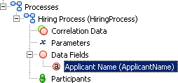
Note: When you type a name in the Label box the name is repeated in the Name box without spaces. The Label appears in the Project Explorer and is followed by the Name in the parentheses.
-
Repeat this Process for the following fields:
-
Applicant Age (Integer Number, Length=3)
-
Accepted (Boolean)
-

Add Conditional Sequence Flow Script
The Boolean Data Field Accepted is used to determine if applicant will be scheduled for an interview.
To do this,
1. Select the Sequence flow that connects Accept Applicant? Exclusive Data-Based Gateway to the Interview Applicant User Task in the Hiring Process.

Trouble Shooting:
If JavaScript is not in the Script Defined As: drop-down ensure that:
-
You have Solution Design enabled.
-
Your Process’ Destination Property is set to iProcess.
-
Select JavaScript from the Script Defined As: drop-down on the Properties tab.
-
Type “Accepted;” in the Describe Sequence Flow Condition box.
Note: Once you select “iProcess” as the Destination Property for your Process, Workflow Studio will show problems in the Problems tab.
Objects on your Process with errors will have an  icon in the top right corner.
Hover your mouse over the icon to view the error message and any quick fix suggestions that may be available.

Create Participants
Note: Participants can be of Type: ROLE, HUMAN, ORGANIZTIONAL UNIT and SYSTEM.
It is recommended that you use ROLE rather than HUMAN to define a Participant for a User Task.
Trouble Shooting: All ROLE, HUMAN and SYSTEM Participants must be defined in the TRANSFLO® Workflow Workspace.
To add Participants to your Process,
1. In the Project Explorer right-click on Participants under the Hiring Process.
Select Participant from the New context sub-menu.

2. In the New Participant dialog box opens.
Type the name of your Participant’s Role (in this case “Hiring Manager”) in the Name box, and select the ROLE radio button.
Click Finish.

3. Repeat this to create the Participant Role “Administrator”.

Adding Participants to User Tasks
All User Tasks must have Participants who will interact with a Form make decisions that can affect routing in subsequent Tasks.
To add Participants to your user tasks do the following:
1. Select the Review Application User Task.
2. In the Properties tab, click on the ellipsis  button next to the Participants box.
3. The Select Participants dialog opens.
Select both the Administrator and the Hiring Manager, and click the Add button.
Click OK.
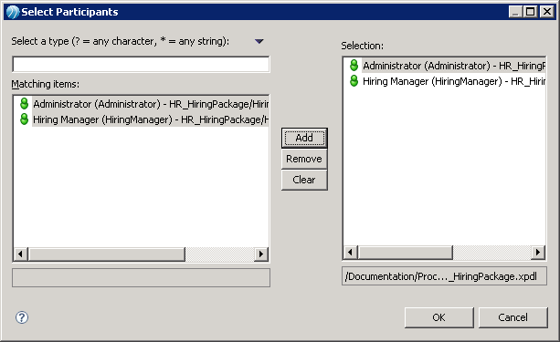
4. The Participants are listed in the Participants box.

5. Repeat for the Interview Applicant User Task.
6. Save your work.
Creating Forms
User Tasks are performed by people, so they require user interfaces.
Workflow Forms provides user interfaces to User Tasks.
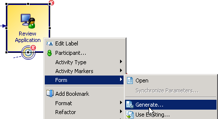
To create a Workflow form perform the following steps:
1. Right click on the Review Application task in the Hiring Process and select Form> Generate from the context menu.
2. The Task Parameter Selection Page opens.
Since all three Fields are going to be used click Finish.

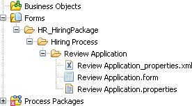
3. A Form hierarchy is created in the Project Explorer with the name of the Package and Process that it belongs to.
Below these is a folder with the same name as the step the Form belongs to.
This folder contains the files required to define the Form.
4. TRANSFLO® Workflow Studio generates a Form for you with three Panes.

The top Pane has data entry fields corresponding to the Data Fields and the corresponding data types that you created above.
The second Pane has the default Navigation buttons and the third Pane is a place holder for validation error messages.
5. Click on the outer edge of the Validation Pane and drag it above the Data Entry Pane.
When a solid horizontal line appears above the Review Application label drop the Validation Pane there.

6. Repeat this for the Navigation Buttons Pane.
Click on the outer edge of the Navigation Buttons Pane and drag it above the Validation Pane.

The default Navigation Button actions are listed in the table below:
| Button | Action |
|---|---|
|
Cancel |
The Cancel button closes the form, does not save the changes made on the Form, and keeps the Case in the current Queue (User Task). |
|
Close |
The Close button closes the form, saves the changes made on the Form, and keeps the Case in the current Queue (User Task). |
|
Submit |
The Submitbutton closes the form, saves the changes made on the Form, and moves the Case to the next step in the Process. |
7. To clarify the action of the Close button you will change the label to make it more descriptive.
Click on the Close button control in the Form to select it.
In the Properties view change the Label property text to “Keep”.
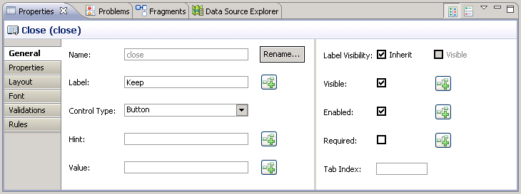
8. The button label is changed.

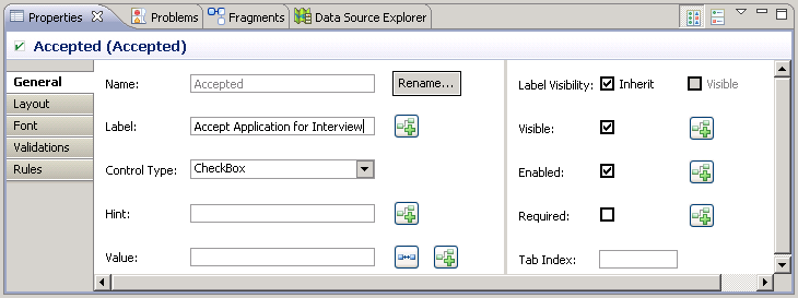
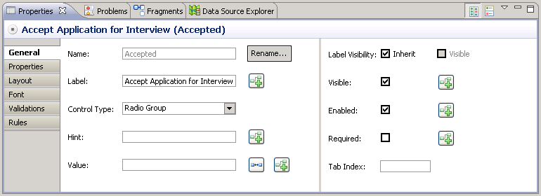
9. The meaning of the label “Accepted” is also unclear.
Click on the Accepted control in the form to select it.
In the Properties view change the Label property text to “Accept Application for Interview”.
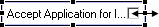
10. The label has changed but part of it is not visible.
Hover over the end point to the right until it becomes a double arrow and drag it to the right to re-size it to the width of the Data Entry Frame.
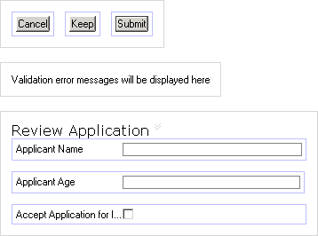
11. The contents of the form should look something like the diagram below.
Notice that the label still seems to be hidden.
12. Save your work.
Note: To change the Data Field populated by a control, click on the  button and select a Data Field from the list.
13. Next, change the check box to two radio buttons.
In the Properties View under the Generaltab change the Control Type property to Radio Group.
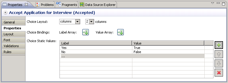
14. In the Properties tab of the properties view change the following properties:
| Property | Value |
|---|---|
|
Choice Layout |
columns |
|
Columns |
2 |
|
Choices |
Specify Static Choices Label = Yes; Value = True. Label = No; Value = False. |
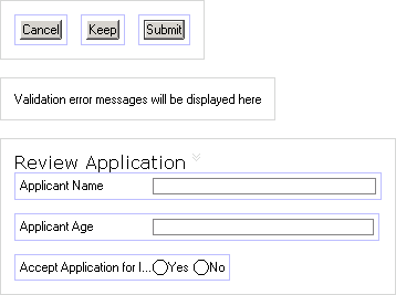
15. Your Form design has changed as shown below:
16. Save your work.
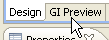
17. To preview what your form will look like, click on the GI Preview tab on the bottom left edge of the Form Design View.
Note: You can test your form in GI Preview mode by entering values in your Form Fields.
The System Log pane will show the Data Fields that are being populated by the Form Fields and the values for each.
18. The Form opens as it would for an end user.
Notice that all of the text for the Accept radio button control is visible.

Using Custom Scripts
Note: This section is intended for advanced Users.
TRANSFLO® Workflow allows you to use VBScript to write custom scripts and insert them in your Workflow Processes.
Custom scripts use the TRANSFLO® Scripting Agent that is packaged in the TRANSFLO® System Agent during TRANSFLO® Server installation.
To insert a custom script in your Process do the following:
1. Place a Manual Task in your Process.
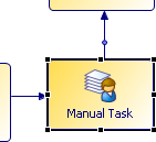
2. Change the label Manual Task, and select a Participant.
3. Log in to your TRANSFLO® Administration Tool, and click Agent Configuration in the tree view menu.
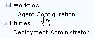
4. The Workflow Agent Configuration page opens in the right frame.
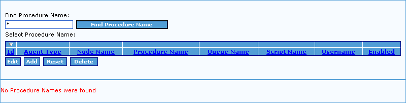
5. Click the Add button to configure a new script.
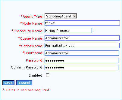
The Workflow Agent Configuration opens.
-
Select the Workflow Agent type from the Agent Type drop-down.
The available Workflow Agent types are: DListAgent, MDPAgent, and ScriptingAgent.
-
Type “TFLOWF” in the Node Name box.
-
Type the name of the Workflow Process in the Procedure Name box.
-
Type the name of the Workflow Queue that the script will interact with in the Queue Name box.
-
The Script Name box is only available if you selected ScriptingAgent from the Agent Type drop-down.
Type the script file name in the Script Name box.
-
Type the Username that will be used by the Workflow Agent to connect to work flow and execute the script in the Username box.
This user must have access to the Workflow Queue you specified above.
-
Type the Password for the Username in both the Password and Confirm Password boxes.
-
Ensure that the script is enabled by checking the Enabled check box.
-
Click Save.
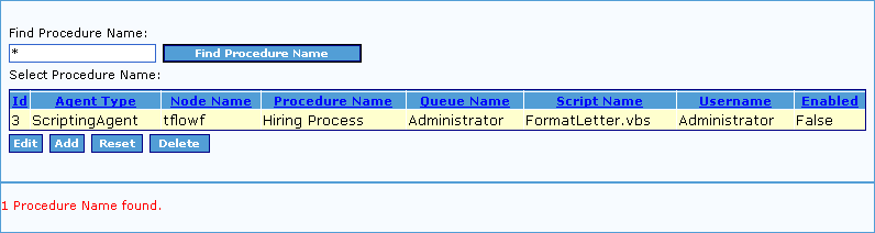
6. Your new script appears in the Workflow Agent Configuration list.
7. Repeat this process for all scripts used by your procedures.
8. To filter the list enter search text using * or % as wild cards in the Find Procedure Name box, and click the Find Procedure Name button.
9. To revert back to the unfiltered list, click the Reset button.
10. To edit an existing script click the Edit button.
11. To delete and existing script click the Delete button.
Scripting Agent Methods and Properties
The TRANSFLO® Scripting Agent support the following standard TRANSFLO® Logging Levels:
1 = Log Errors only
2 = Log Errors and Warnings
3 = Log Errors, Warnings and Processing Information
4 = Log Errors, Warnings, Processing Information and Trace
The Scripting Agent supports various methods, classes and properties as listed below:
Methods
| Definition | Description |
|---|---|
|
LogInfo(string msg) |
Writes the argument msg to the log file when system agent log level is set to 3 or 4. |
|
LogWarning(string msg) |
Write the argument msg to the log file when system agent log level is set to 2, 3 or 4. |
|
LogError(string msg) |
Writes the argument msg to the log file when system agent log level is set to any value. |
|
GetCaseFieldValue(string FieldName) |
Returns the Case Field value for the FieldName parameter that is passed in. |
|
SetCaseFieldValue(string FieldName, object FieldValue) |
Sets the Case Field value. To modify any Case Field you can use this method by specifying the Field name and value. |
Class
| Name | Description | |
|---|---|---|
|
CaseField |
string Name |
Name of the Workflow Field. |
|
object Value |
Value of the Workflow Field. |
|
|
CaseFieldType Type |
Type of workflow field, possible types are: Bool, Int, Double, String, and DateTime. |
iProcess system values can be used in your process scripts and can be passed to the scripting engine. In JavaScript, you can assign these values to your process fields and retrieve them later.
Syntax:
< case field name > = < iProcess System Values >
-
<case field name> is a field in your process
-
<iProcess System Values> is a system value from the iProcess system value definitions table below.
Example:
MyCaseNumber = SW_CASENUM
MyCaseNum is a field on the plan.
The following system values are defined and available for your use:
| Value | Description |
|---|---|
|
SW_ANYTHING |
(any type) any value. This may only be used as validation for a field marking. It means that as well as other values specified in the validations, you may enter any value into the field. |
|
SW_BLANK |
(text) a null text constant, i.e. "". (Note that this is not the same as SW_NA - see below.) |
|
SW_CASEDESC |
(text) case description. |
|
SW_CASENUM |
(numeric) case number. |
|
SW_CASEREF |
(text) case reference (pp-nn). |
|
SW_DATE |
(date) current system date. |
|
SW_GEN_IDX |
(numeric) generic array field if an array field's individual index is unassigned. |
|
SW_HOSTNAME |
(text) host name for the procedure. |
|
SW_NA |
(any type) Not Assigned - a field has no value. |
|
SW_NODENAME |
(text) node name of the system. |
|
SW_PRODESC |
(text) procedure description. |
|
SW_PRONAME |
(text) name of the procedure. |
|
SW_QPARAMn |
(text) application specific data which can be used in Work Queue Manager to display, sort or filter work queues. Four fields are available: SW_QPARAM1 to SW_QPARAM4. Refer to “Organizing Your Work Item Lists” in the TIBCO iProcess Workspace (Windows) User's Guide, for more information about the use of these fields. |
|
SW_QRETRYCOUNT |
(numeric) number of times that a message in a message queue has failed. The field value is 0 the first time a message is processed, and is incremented each time the message fails. For example, if a BG process is processing a message and SW_QRETRYCOUNT = 2, this means that the BG is attempting to process the message for the third time.
|
|
SW_STEPDESC |
(text) description of the step. |
|
SW_STEPNAME |
(text) name of the step. |
|
SW_TIME |
(time) current system time. |
The following system values are relevant to sub-procedures:
| Value |
Description |
|---|---|
|
SW_MAINCASE |
Top level procedure’s case number. |
|
SW_MAINPROC |
Top level procedure’s name. |
|
SW_MAINHOST |
Host where top level procedure resides. |
|
SW_PARENTCASE |
Parent procedure’s case number. |
|
SW_PARENTPROC |
Parent procedure’s name. |
|
SW_PARENTHOST |
Host where parent procedure resides. |
|
SW_PARENTREF |
Internal information on parent. |
The following system values are relevant to case prediction:
|
Value |
Description |
|---|---|
|
SW_ARRIVALDATE |
(date) The date when case prediction has calculated the step will arrive in the queue. |
|
SW_ARRIVALTIME |
(time) The time when case prediction has calculated the step will arrive in the queue. |
|
SW_LEAVEDATE |
(date) The date when case prediction has calculated the step will leave the queue. |
|
SW_LEAVETIME |
(time) The time when case prediction has calculated the step will leave the queue. |